Shipwrights & Boatbuilders
Project Restorations

Re-Build ~ New Build ~ Repair

Updated: 27 April 2012
S130
WW2 Schnellboot S130     WW2 Schnellboot S130
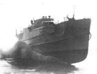
WW2 German Schnellboot Restoration
 

Reconstruction - Part 5
Hull
Timber Work


Hull Structure


August, September 2011

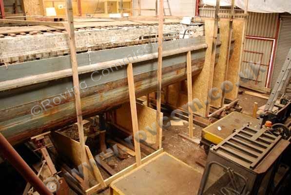
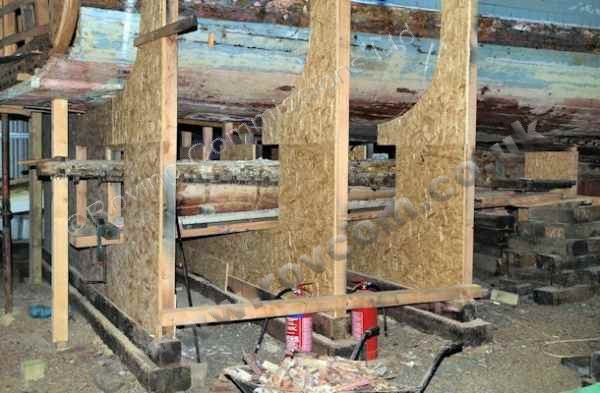
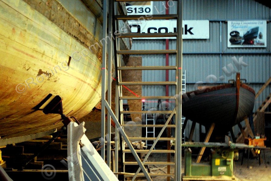
Support Cradling at the Stern


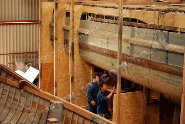
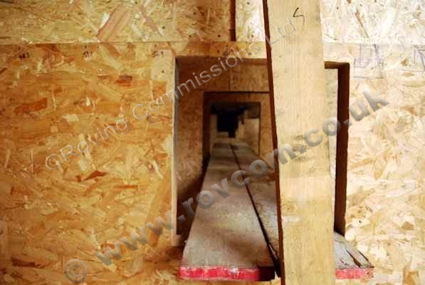
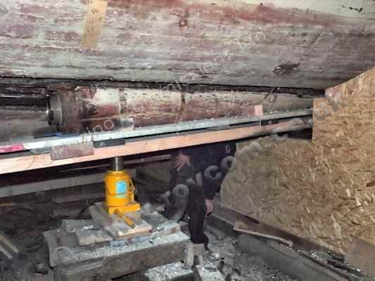
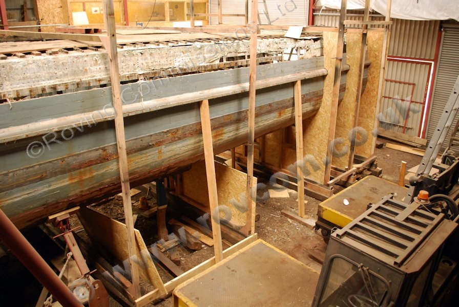
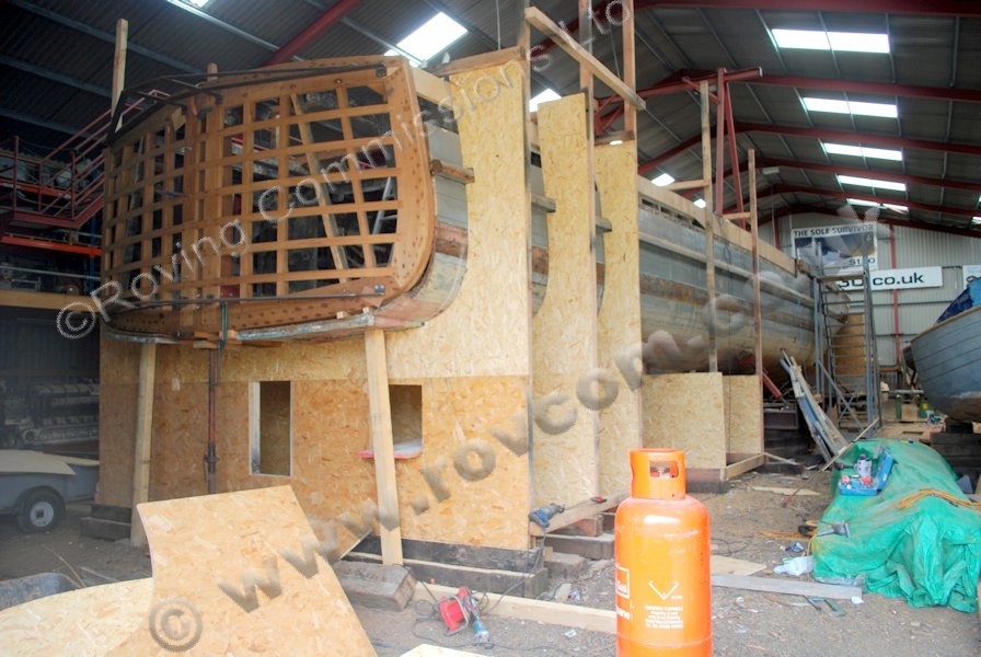
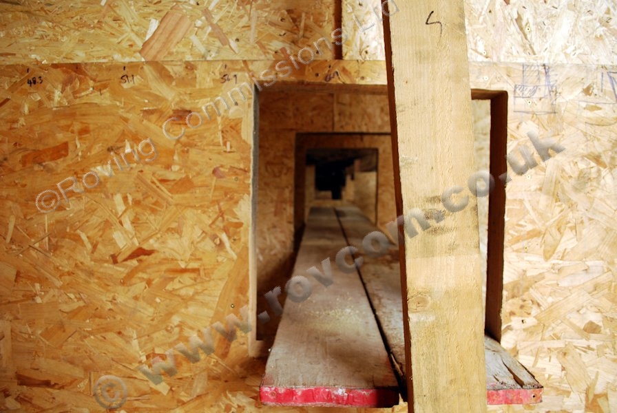
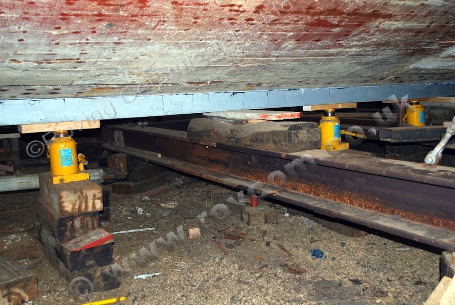
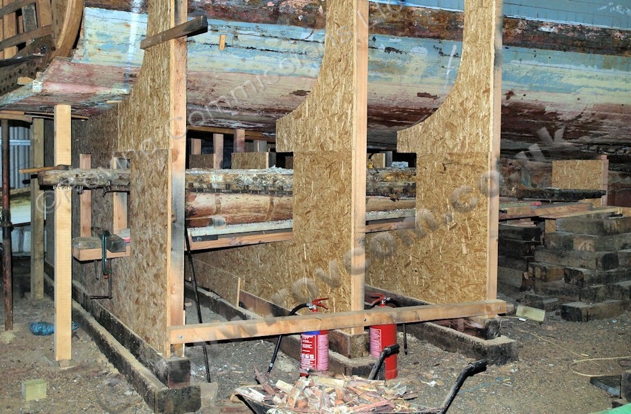
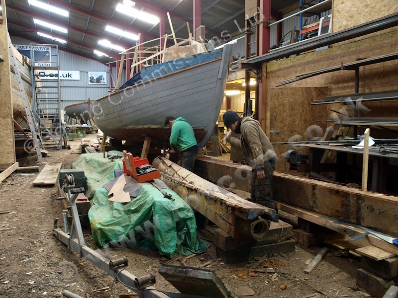
Over time, through drying out and weakening from dismantling, the hull at the stern was beginning to sag at the turn of the bilge. Support cradling has been installed to stop any further movement. Ports have been built into the support bulkheads behind each shaft to allow the shaft logs to be extracted.

S130 - Support cradling being installed under the stern

""

S130 - Support cradling being installed under the stern S130 - Support cradling being installed under the stern />

S130 - Support cradling being installed under the stern

""

S130 - Support cradling being installed under the stern S130 - Support cradling being installed under the stern />

S130 - Support cradling being installed under the stern

""

S130 - Support cradling being installed under the stern S130 - Support cradling being installed under the stern />

S130 - Ports installed in the support cradling to allow the shaft logs to extracted

""

S130 - Ports installed in the support cradling to allow the shaft logs to extracted S130 - Ports installed in the support cradling to allow the shaft logs to extracted />

S130 - Ports installed in the support cradling to allow the shaft logs to extracted

""

S130 - Ports installed in the support cradling to allow the shaft logs to extracted S130 - Ports installed in the support cradling to allow the shaft logs to extracted />


October, December 2011


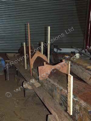
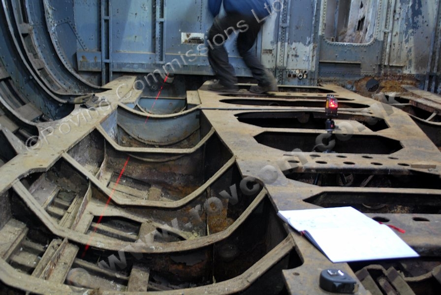
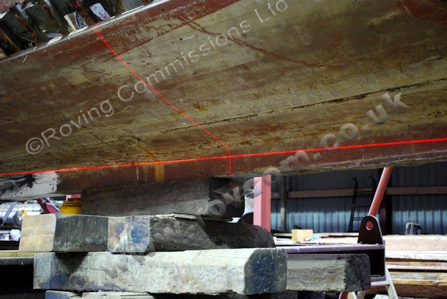
Before removing the shaft logs it would be necessary to check their position and alignment compared to that shown on the lines plan.


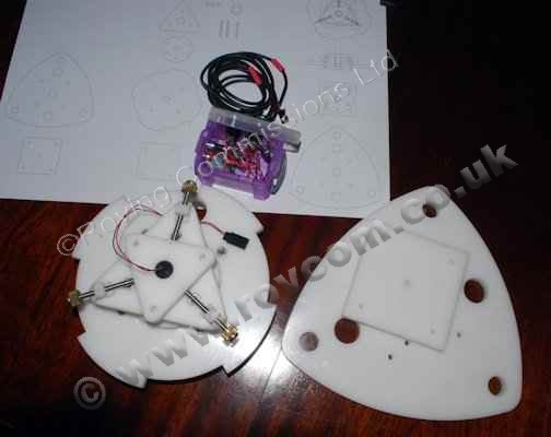
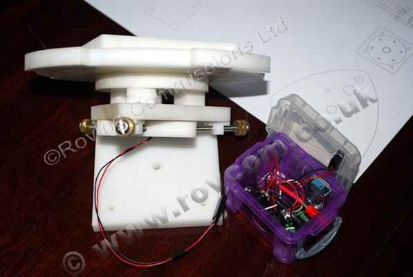
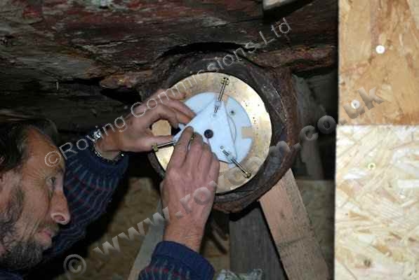
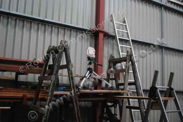
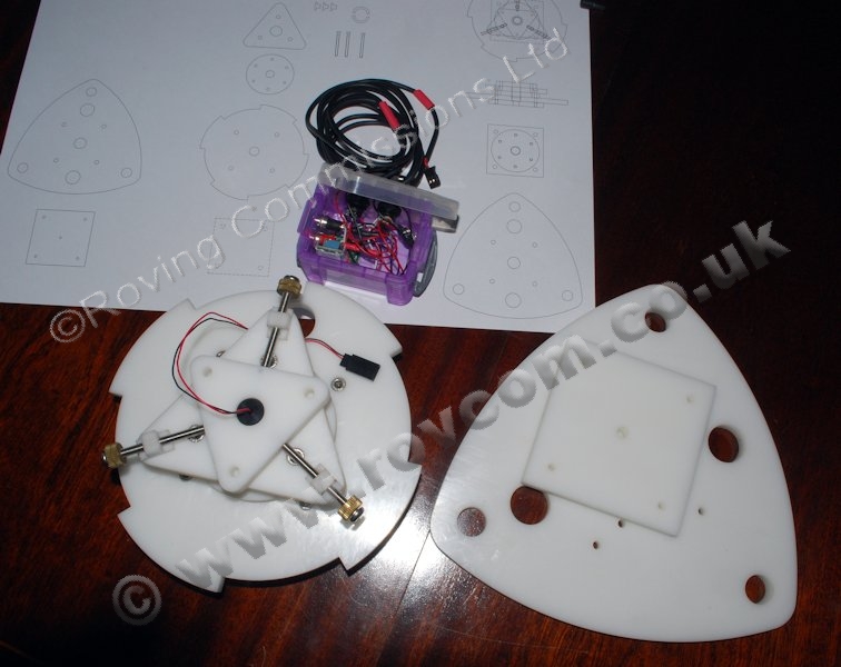
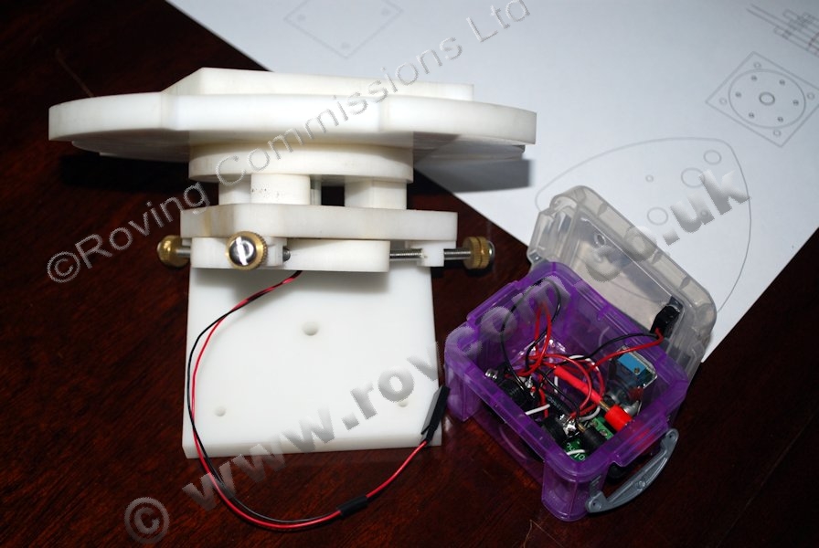
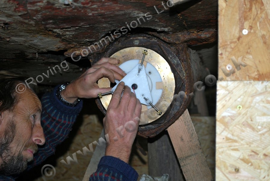
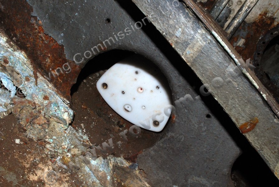
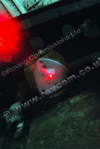
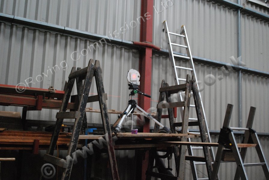
In order to carry out this excersise we could either use a string line or employ the use of a laser. As we would have a number of alignment tasks to accomplish, a laser was the obvious choice. Alignment lasers tend to be somewhat over complicated and expensive when our requirement called for nothing more complicated than a simulated string line. After considerable research, we decided to make our own unit consisting of a powerful, focusable laser diode in a custom mount which could be installed in one end of the stern tubes with a target in the other end. With other mounting arrangements the laser could be used on a tripod and on the boring table.

S130 - Making the alignment laser

""

S130 - Making the alignment laser S130 - Making the alignment laser />

S130 - Making the alignment laser

""

S130 - Making the alignment laser S130 - Making the alignment laser />

S130 - Installing the alignment laser in a stern tube

""

S130 - Installing the alignment laser in a stern tube S130 - Installing the alignment laser in a stern tube />

S130 - Alignment Laser: Inboard stern tube target

""

S130 - Alignment Laser: Inboard stern tube target S130 - Alignment Laser: Inboard stern tube target />

S130 - Firing up the alignment laser

""

S130 - Firing up the alignment laser S130 - Firing up the alignment laser />

S130 - Alignment Laser: Finding the shaft line

""

S130 - Alignment Laser: Finding the shaft line S130 - Alignment Laser: Finding the shaft line />

S130 - Alignment Laser: Finding the shaft lines

""

S130 - Alignment Laser: Finding the shaft lines S130 - Alignment Laser: Finding the shaft lines />


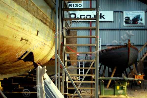
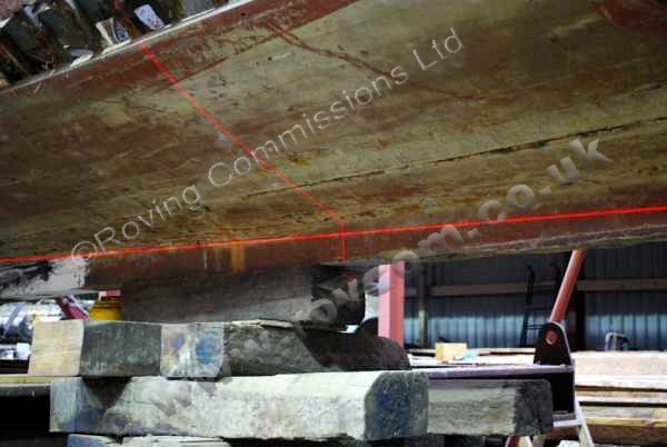
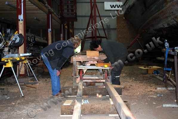
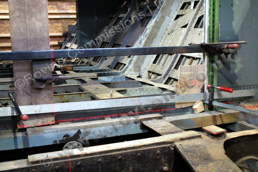
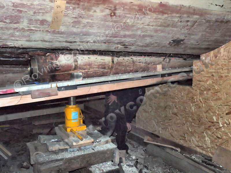
Our initial measurements indicated that there was a significant difference between the port and starboard shaft lines and that the angle of all three shaft lines were running too low. This indicated that the keel line was not running true there may be some twist in the hull.


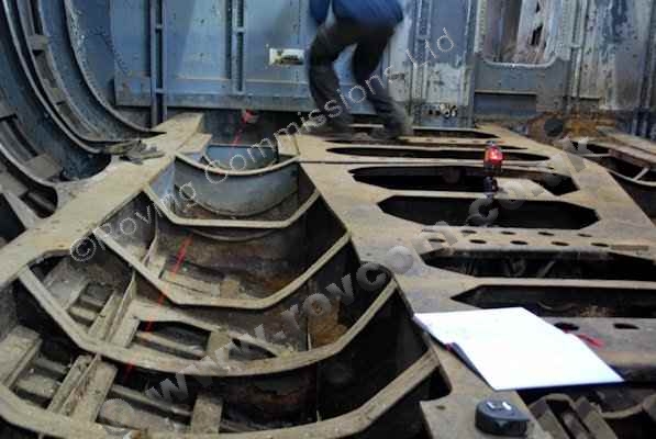
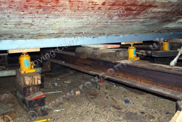
In order to find and correct the problem we would need to locate the design warterline both inside and outside the boat. For this purpose we set up our aligmrnent laser and used a horizontal/vertical laser level at a number design stations over the length and compared the waterline height measured off the lines plan with that of the boat. Once we had sufficient information, we jacked up or lowered the keel as required, while constantly checking the thwartsips level. This process was repeated a number of times until the boat was brought to within suitable tollerances. In the final analysis, we achieved a declivity of 0.018m over 34.9m and a variance (keel rabbet to waterline) of 6mm-10mm.


On checking the shaft lines we finally achieved a set of measurements in accordance with the lines plan so work on extracting the old shaft logs and making new replacements could commence.

S130 - Setting up the alignment laser to the waterline

""

S130 - Setting up the alignment laser to the waterline S130 - Setting up the alignment laser to the waterline />

S130 - The laser aligned to the waterline

""

S130 - The laser aligned to the waterline S130 - The laser aligned to the waterline />

S130 - Checking the keel line relative to the waterline

""

S130 - Checking the keel line relative to the waterline S130 - Checking the keel line relative to the waterline />

S130 - Correcting the keel line

""

S130 - Correcting the keel line S130 - Correcting the keel line />


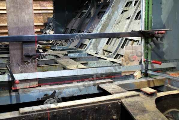
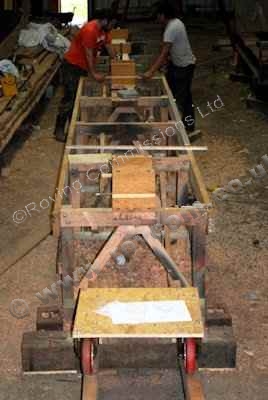
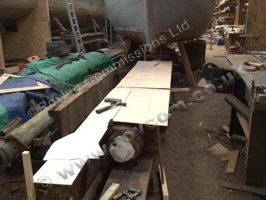
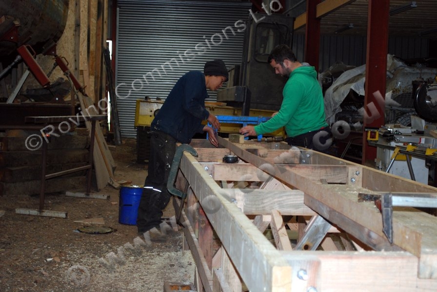
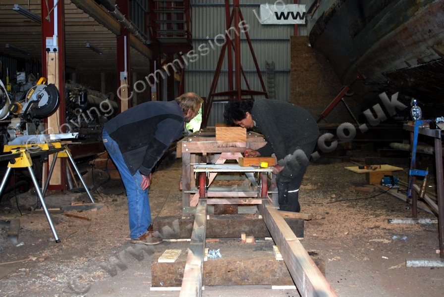
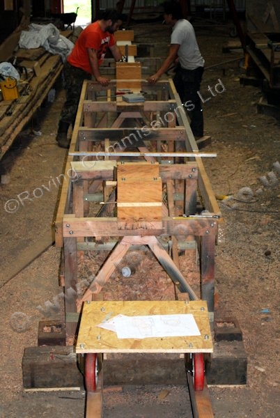
A hole with a diameter of 206mm will have to bored for a length of 4m through the shaft logs. In preparation for making and boring the replacement shaft logs, an accurately level boring table has been constructed on which the logs will be bored to accept the stern tubes. A pair of plummer block bearings are mounted at each end to support the boring bar and rails have been laid up to one end, on which a heavy duty, trolley mounted, drill will run.

S130 - Constructing the shaft log boring table

""

S130 - Constructing the shaft log boring table S130 - Constructing the shaft log boring table />

S130 - Constructing the shaft log boring table

""

S130 - Constructing the shaft log boring table S130 - Constructing the shaft log boring table />

S130 - Constructing the shaft log boring table

""

S130 - Constructing the shaft log boring table S130 - Constructing the shaft log boring table />


January, February 2012


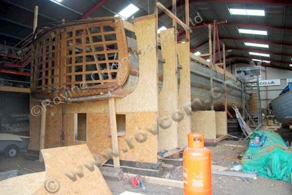
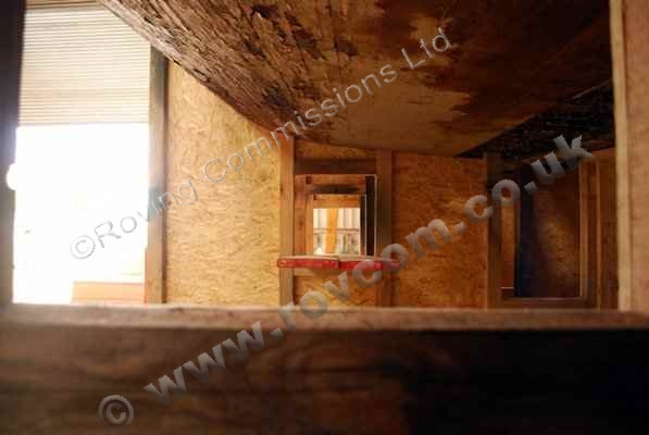
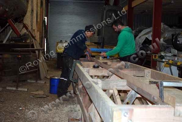
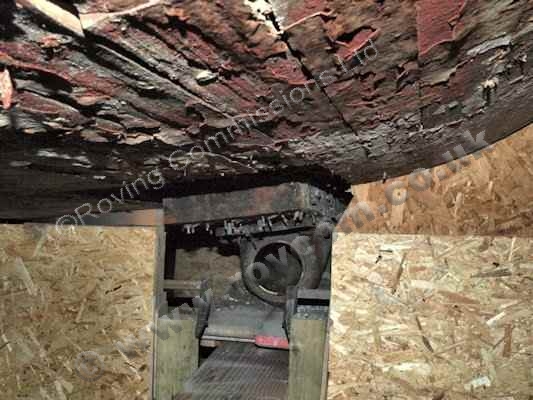
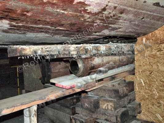
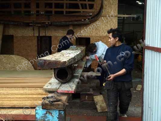
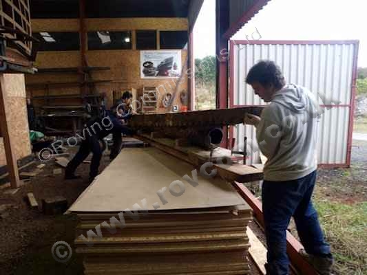
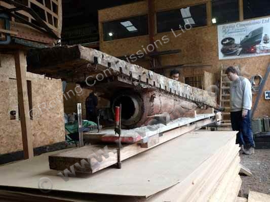
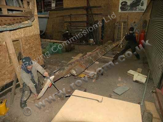
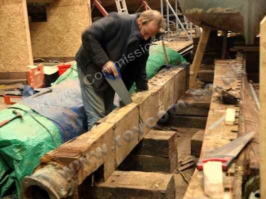
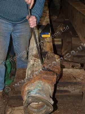
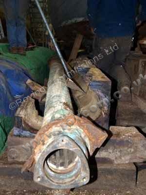
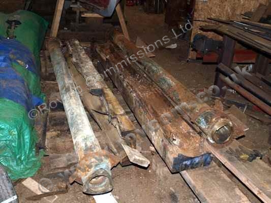
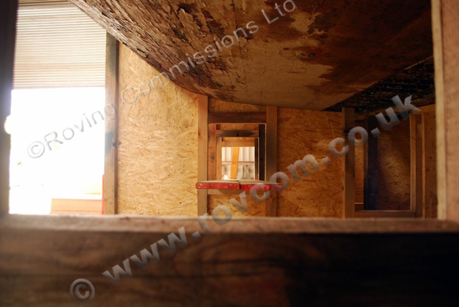
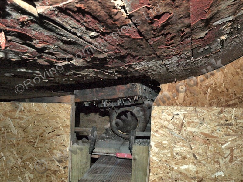
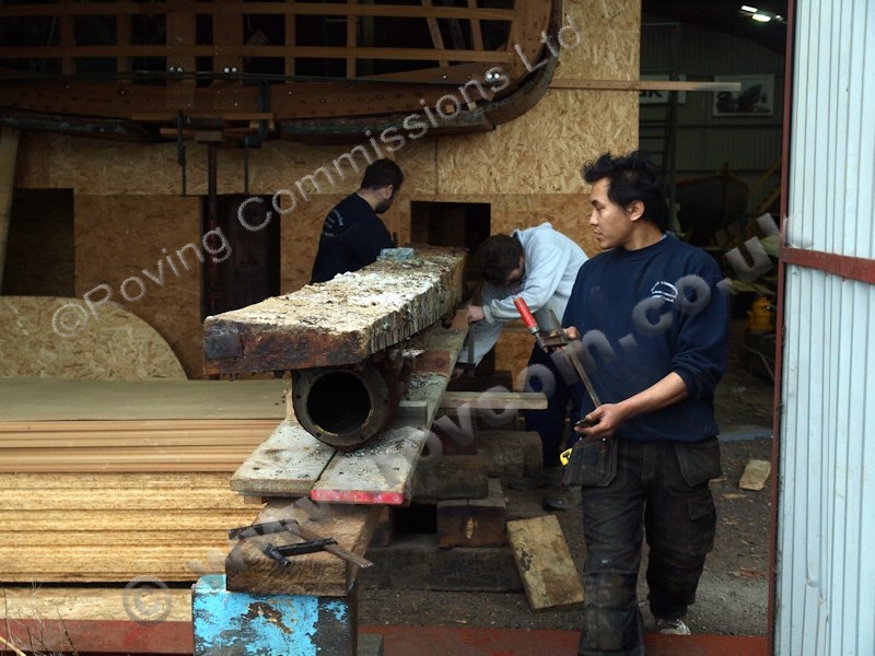
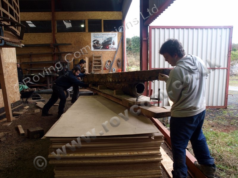
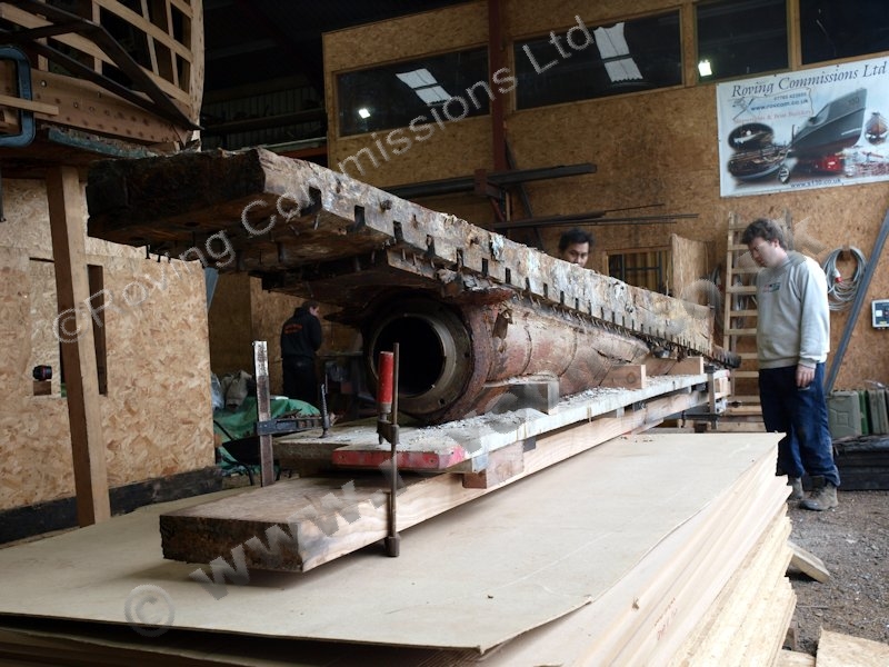
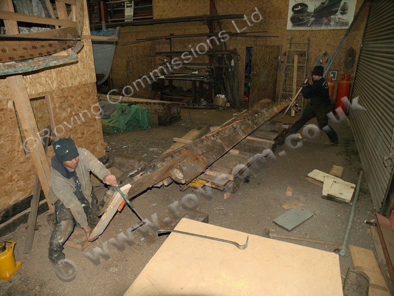
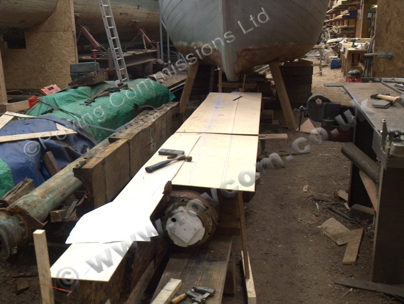
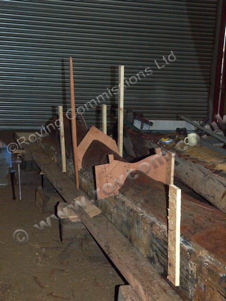
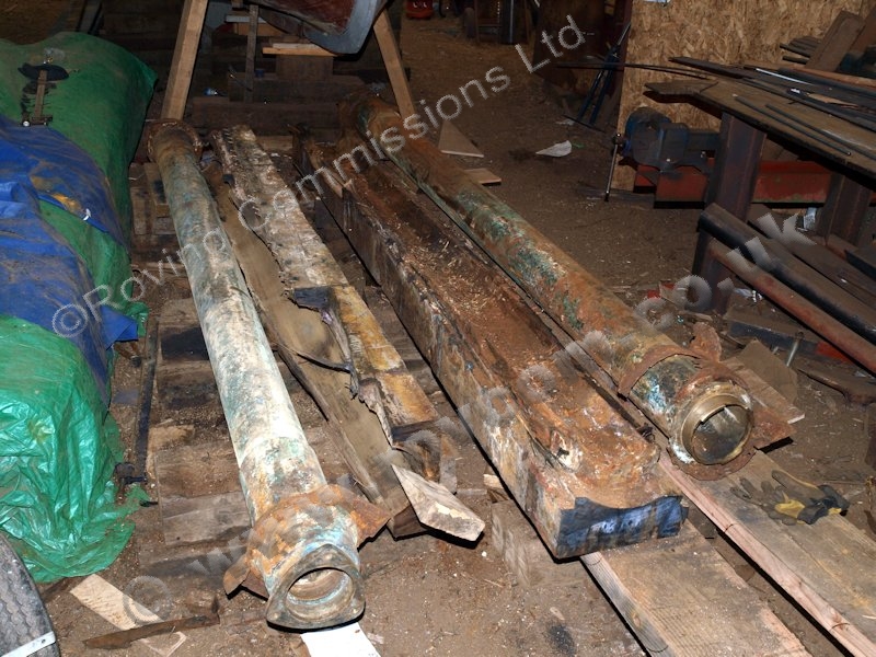
The hull planking inway of the wing shaft logs was removed along with the aluminium metal work and adjacent timber ends before the logs were lowered onto a 'skateboard' fabricated from scaffold boards attached to rollers. The logs lowered onto the 'skateboard' and rolled down the ramp and out through the support bulkheads. Once out, they were turned and transferred to a trolley and stowed ready to lift patterns.

S130 - Extracting the starboard shaft log on a skateboard

""

S130 - Extracting the starboard shaft log on a skateboard S130 - Extracting the starboard shaft log on a skateboard />

S130 - Extracting the starboard shaft log on a skateboard

""

S130 - Extracting the starboard shaft log on a skateboard S130 - Extracting the starboard shaft log on a skateboard />

S130 - Extracting the starboard shaft log on a skateboard

""

S130 - Extracting the starboard shaft log on a skateboard S130 - Extracting the starboard shaft log on a skateboard />

S130 - Extracting the starboard shaft log on a skateboard

""

S130 - Extracting the starboard shaft log on a skateboard S130 - Extracting the starboard shaft log on a skateboard />

S130 - Extracting the starboard shaft log on a skateboard

""

S130 - Extracting the starboard shaft log on a skateboard S130 - Extracting the starboard shaft log on a skateboard />

S130 - Turning the shaft log

""

S130 - Turning the shaft log S130 - Turning the shaft log />

S130 - The shaft log is out

""

S130 - The shaft log is out S130 - The shaft log is out />

S130 - Transferring the shaft log

""

S130 - Transferring the shaft log S130 - Transferring the shaft log />

S130 - Making patterns from the shaft log

""

S130 - Making patterns from the shaft log S130 - Making patterns from the shaft log />

S130 - Making patterns from the shaft log

""

S130 - Making patterns from the shaft log S130 - Making patterns from the shaft log />


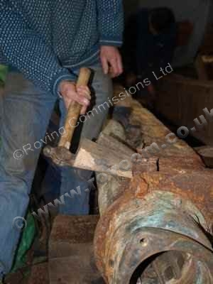
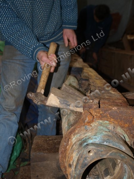
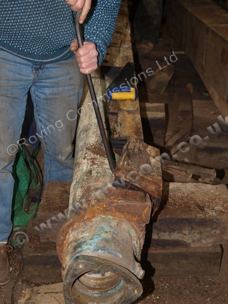
With patterns and all information taken off the shaft logs, the stern tubes were carefully broken out to be transported to Wheatcroft HQ for disassembly and cleaning prior to being reinstalled in the new logs.

S130 - Breaking out the stern tubes

""

S130 - Breaking out the stern tubes S130 - Breaking out the stern tubes />

S130 - Breaking out the stern tubes

""

S130 - Breaking out the stern tubes S130 - Breaking out the stern tubes />

S130 - Breaking out the stern tubes

""

S130 - Breaking out the stern tubes S130 - Breaking out the stern tubes />

S130 - Breaking out the stern tubes

""

S130 - Breaking out the stern tubes S130 - Breaking out the stern tubes />

S130 - Breaking out the stern tubes

""

S130 - Breaking out the stern tubes S130 - Breaking out the stern tubes />

S130 - Breaking out the stern tubes

""

S130 - Breaking out the stern tubes S130 - Breaking out the stern tubes />


Back      Next